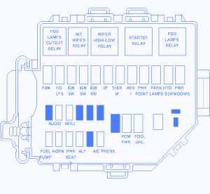
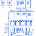
| FUSE POSITION | AMPS | CIRCUITS PROTECTED |
|---|---|---|
| FAN (3.8L) | 30A (C.B) | Constant Control Relay Module |
| FAN (4.6L) | 50A (Maxi) | Constant Control Relay Module |
| HD-LPS | 30A (Maxi) | Main Light Switch, Multifunction Switch |
| IGN SW | 40A (Maxi) | Starter Motor Relay, Intake Runner Control Module, GEM, Overdrive Cancel Switch, Instrument Cluster |
| IGN SW | 40A (Maxi) | ABS Module, Instrument Cluster, Reversing Lamps, Speed Control Servo, GEM, Shift lock Actuator, A/C Heater, Power Windows, Radio, Raise Relay, Lower Relay, Whindshield Wiper Motor, Intermittent Wiper relay, Wiper High/Low Relay |
| IGN SW | 40A (Maxi) | Restraint Control Module, DRL Module, A/C Heater, Blower Motor, Electronic Flasher |
| I/P | 40A (Maxi) | Instrument Cluster, PCM |
| THERM | 30A (Maxi) | Secondary Air Injection |
| ABS 1 | 50A (Maxi) | ABS Module |
| POWER POINT | 20A (maxi) | Auxiliary Power Point |
| PARK LAMPS | 30A (Maxi) | Main Light Switch |
| HTD EL | 30A (Maxi) | Rear Window Defrost Control |
| POWER WINDOWS | 40A (Maxi) | GEM, Power Door Locks |
| AUDIO | 10A (Mini) | Radio, CD PLAYER |
| ABS 2 | 20A (Miini) | ABS Module |
| FUEL PUMP | 20A (Mini) | Fuel Pump Relay |
| HORN | 20A (Mini) | Horn, Horn Relay |
| POWER SEATS | 25A (Mini) | Power Seat Switch |
| ALT | 20A (Mini) | Generator |
| A/C PRESS | 20A (Mini) | Constant Control Relay Module |
| PCM POWER | 30A (Maxi) | Intake Manifold Runner Control |
Ford Mustang 1999 Fuse Panel/Board – Fuse Symbol Map

