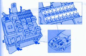
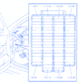
| Location | Components | Amperage |
|---|---|---|
| 1 | Engine Control Module, Automatic Transmission Control Module | 5A |
| 2 | A/C Relay | 5A |
| 3 | Relay, Air Pump, Heated Oxygen Sensor | 15A |
| 4 | Fuel Pump | 15A |
| 5 | Fuel Injection, Mass Air Flow (MAF) Sensor, Idlle Air Control System, Engine Control Module | 15A |
| 6 | Automatic Transmission Control Module | 15A |
| 7 | Ignition Coil | 25A |
| 8 | Foglights | 25A |
| 9 | Spare | - |
| 10 | Positioning/Parking Lights, Left | 15A |
| 11 | Positioning/Parking Lights, Right | 15A |
| 12 | Left High Beam | 15A |
| 13 | Right High Beam, Instrument Panel | 15A |
| 14 | Left Low Beam | 15A |
| 15 | Right Low Beam | 15A |
| 16 | A/C Compressor | 15A |
| 17 | Horn | 15A |
| 18 | Accessories (See Resprective Accesories Instructions) | 15A |
Volvo 850 1997 Fuse Panel/Board – Fuse Symbol Map

