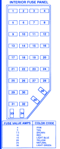
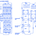
| FUSE POSITION | AMPS | CIRCUIT PROTECTED |
|---|---|---|
| 1 | 7.5A | Power Antenna Module, Power Mirror Switch (Power Supplied Through MaxiFuse 13) |
| 2 | 7.5A | High Mount Stop Lamps |
| 3 | 15A | Headlamp Switch, Park Lamp Relay, Dimmer Relay (Power Suplied Through MaxiFuse 8) |
| 4 | 10A | LH Headlamp Lampout warning Module (Power Suplied Through the Multi-Function Switch) |
| 5 | 10A | Data link Connector (Power Supplied Through MaxiFuse13) |
| 6 | 7.5A | Airbag Diagnostic Monitor, Blower Motor Relay, EATC Module |
| 7 | 7.5A | Dimmer Module (Power Supplied Through the Park Lamp Relay) |
| 8 | 10A | RH Headlamp, DRL, Foglamp Relay, Lampout Warning Module (Power Supplied Through the Multi-Funtion Switch) |
| 9 | 10A | Autolamps (Power Supplied Through MaxiFuse 13), Memory seat Module, Message Center, EATC Module, Cellular Telephone |
| 10 | 7.5A | Blend Door Actuator, GEM, Shift Lock Actuator, Brake Pressure Switch, Speed Control/Amplifier Assembly, Overhead Console, Integrated Control Panel, Rear Blower Motor Relay, Steering Rate Sensor ARC Module, lampout Warning module, Mesasge Center |
| 11 | 7.5A | Radio, Dimmer Relay, Instrument Cluster, Autolamps |
| 12 | 10A | Liftgate Wiper/Washer Switch, Front washer Pump Relay |
| 13 | 15A | Brake On/Off Switch (Power Supplied Through MaxiFuse 13) |
| 14 | 10A | 4WABS Main Relay, 4WABS Control Module |
| 15 | 7.5A | Airbag Diagnostic Monitor, Instrument Cluster |
| 16 | 30A | Wiper Run Relay, Wiper Hi-Lo Relay, Wiper Motor |
| 17 | 25A | Cigar Lighter (Power Supplied Through MaxiFuse 13) |
| 18 | 15A | Heater -A/C, EATC Module |
| 19 | 25A | Radio Noise Capasitor, Ignition Coil, PCM Power Diode |
Ford Explorer 1997 Fuse Panel/Board – Fuse Symbol Map

