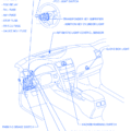
| SYMBOL | DESCRIPTION |
|---|---|
| A12 | A/C Amplifier |
| A13 | A/C Amplifier |
| A14 | A/C Amplifier |
| A15 | A/C Evaporator Temp. Sensor |
| A16 | A/C Room Temp. Sensor |
| A17 | A/C Solar Sensor |
| A18 | ABS ECU |
| A19 | ABS ECU |
| A20 | ABS and Traction ECU |
| A21 | ABS and Traction ECU |
| A22 | ABS and Traction ECU |
| A23 | ABS Lateral Acceleration Sensor |
| A24 | Air Inlet Control Servo Motor |
| A25 | Air Mix Control Servo Motor |
| A26 | Air Vent Mode Control Servo Motor |
| A27 | Airbag Squib (Steering Wheel Pad) |
| A28 | Airbag Squib (Front Passenger Airbag Assembly) |
| A29 | Ashtray Illumination |
| A30 | Auto Antenna Control Relay |
| B3 | Blower Motor |
| B4 | Blower Motor Control Relay |
| B5 | Blower Motor Control Relay |
| B6 | Buckle Sw LH |
| B7 | Buckle Sw RH |
| C5 | Center Airbag Sensor Assembly |
| C6 | Cigarette Lighter |
| C7 | Cigarette Lighter Illumination |
| C8 | Clock |
| C9 | Clutch Start Sw |
| C10 | Combination Meter |
| C11 | Combination Meter |
| C12 | Combination Meter |
| C13 | Combination Sw |
| C14 | Combination Sw |
| C15 | Cruise Control Clutch Sw |
| C16 | Cruise Control ECU |
| D5 | Data Link Connector 2 (TDCL) |
| D6 | Daytime Running Light Relay (Main) |
| D7 | Diode (For Interior Light) |
| D8 | Diode (For Idle-UP) |
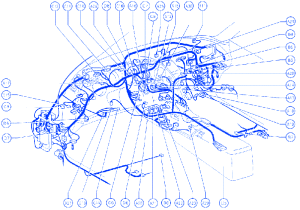
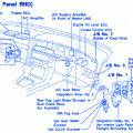
Toyota Supra 1995 For The Amplifier Electrical Circuit Symbol Map

